
Troubleshooting 1968 Ford Thunderbird Sequential Turn Signals
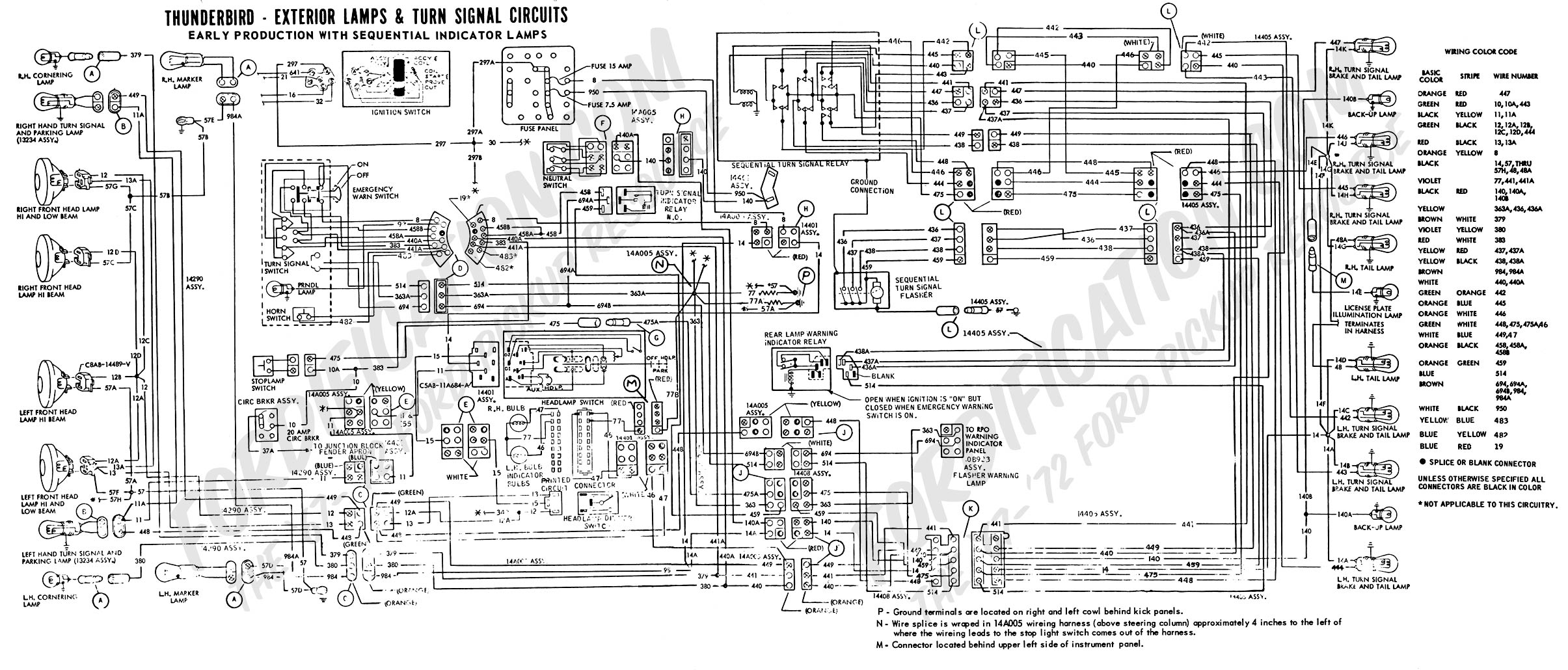
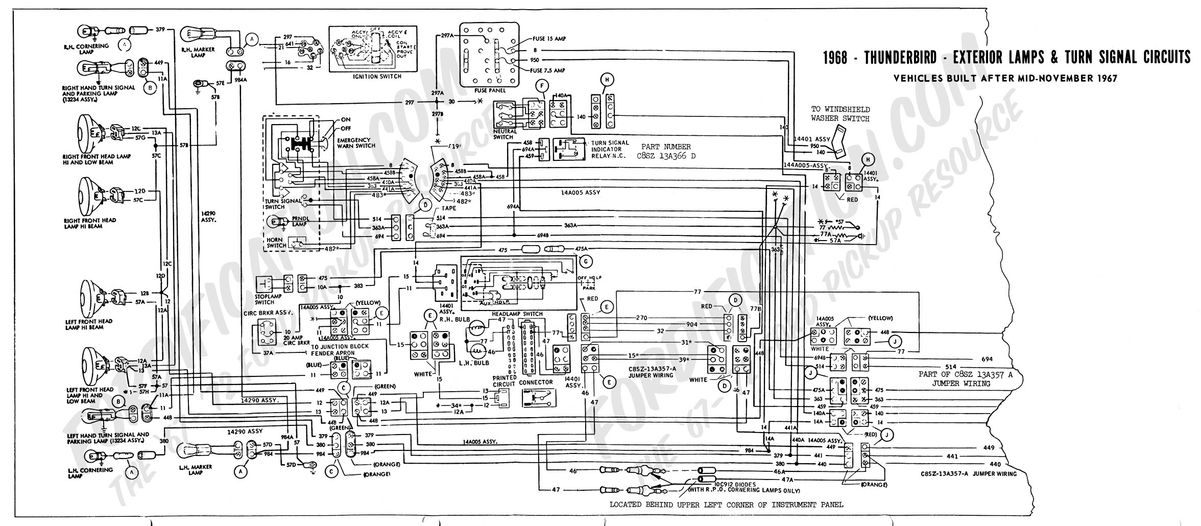
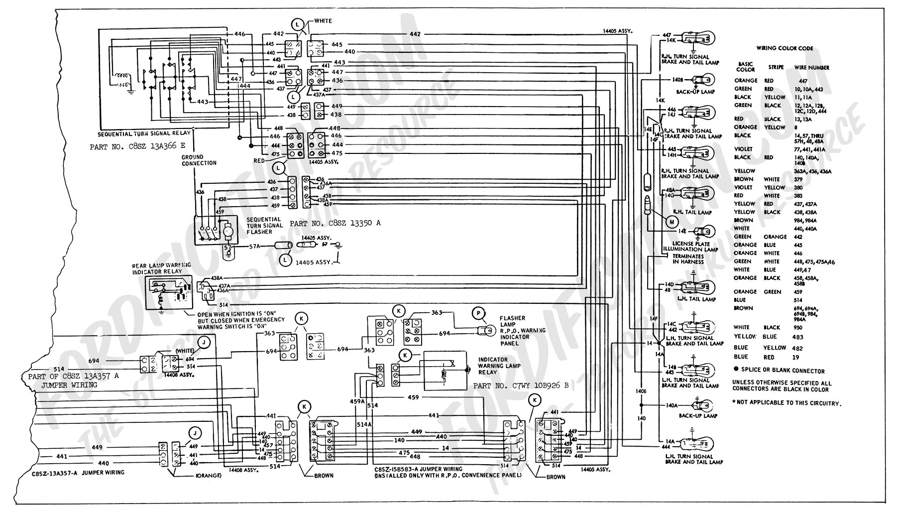
This article covers troubleshooting 1968 and early 1969 (built before 10/15/68) Ford Thunderbird sequential turn signals. The turn signal system has a number of electro-mechanical parts: the turn signal switch, (located in the steering column), a turn signal relay (located on the passenger's side inside firewall), a warning indicator relay (mounted on the rear seat brace), a directional relay, and a motor-driven sequential flasher located in the trunk on the driver's side high up in the fender. The most failure prone parts are the mechanical sequential flasher and the turn signal switch. Circuit diagrams found in the 1968 Ford Thunderbird factory shop manual are incorrect. Refer to the diagrams in Ford TSB 84, Article 1268 from the FORDification.com TSB database website:
Early 1968 Ford Thunderbird Late 1968 Ford Thunderbird pg 1 Late 1968 Ford Thunderbird pg 2
Basically, the system works as follows: when the directional lever on the turn signal switch is moved, it completes circuits that select and feed power to the corresponding bank of lights. Power for the lights is fed through the turn signal indicator relay (located on the passenger's side inside firewall) to the sequential flasher. The flasher has three cams that, when rotated, depress switches corresponding to the inboard, center, and outboard tail lights. The power is then routed to the emergency relay (which connects all lights together for T-Birds) and to the directional relay. This two-sectioned (right and left) relay routes power through to the selected bank of lights. Since brake lights are not sequenced, the directional relay allows all lights to turn on simultaneously when the brake light power feed is energized. But when the turn signal switch is actuated, the brake light power feed is disconnected and the turn signal feed is activated to allow the directional signal to override the brake lights.
On cars built before 11/6/67, the front turn signals flash at the same time as the inboard rear light. On cars built from 11/6/67, the system was revised so that the front turn signals flash at the same time as the outerboard rear light.Now that you understand a little about how your turn signal system works, you can start troubleshooting. You will need a VOM (Volt-Ohm-Meter) and the circuit diagram for your year car. The most common complaints are: no turn signals, one or more lights on but not flashing, one or more lights flashing, and all lights flashing together. The first place to check is the fuse in the fuse box. The next stop is to check all bulbs and their sockets. If these are all good, then now the real sleuthing must begin!
No turn signals (right or left):
When the turn signal lever is depressed, no lights come on
anywhere. A click from the directional relay in the trunk may be heard.
Start by checking for 12V power on the orange/green wire feeding
the motor-driven sequencer in the trunk. Lack of power indicates
either a failed turn signal switch or fuse. If there is no sound,
check for power at the directional relay in the trunk for 12V on
the white wire (LH turn) and purple wire (RH turn).
Next try depressing the emergency switch, if the emergency flashers
work, the turn signal switch is most likely bad. Disconnect the turn
signal switch from the harness and check it according to Table 1
using a VOM or self powered test light. The table shows wire pairs
that should be shorted together with the switch in the indicated
position. If any connections are open, replace the switch. Usually
the switch has failed when the plastic around the riveted contacts
in the area around the emergency button appears to be burnt or melted.
This can only be seen with the steering wheel removed. The turn signal
switch connector pins can also be burnt or oxidized: carefully inspect
the pins on both sides of the connector. Make sure they are all securely
seated into the connector and the connector is not melted or burned.
For more information, review the
Turn Signal Switch Diagnosis Guide.
CENTER POSITION |
LEFT TURN |
RIGHT TURN |
| Green, Orange-Blue | Blue, Green-White | Blue, Orange-Blue |
| Green, Green-Orange | Blue, Green-Orange | Blue, White-Blue |
| Blue, Red | Blue, Red | Blue, Red |
| Green, Orange-Blue | Green, Green-Orange | |
| Brown, Yellow-Black | Brown, Yellow-Black |
Table 1. 1968 Thunderbird Turn signal switch connections
No left turn signals:
With the turn signal switch pushed up, check for 12V power on the white wire feeding the 14-pin directional relay in the trunk. If there is power on it and flashing power on the yellow/yellow-black/yellow-red wires, the relay is bad. If there is no power on the white and orange/green wire, the turn signal switch may be bad.No right turn signals:
With the turn signal switch pushed down, check for 12V power on the purple wire feeding the 14-pin directional relay in the trunk. If there is power on it and flashing power on the yellow/yellow-black/yellow-red wires, the relay is bad. If there is no power on the violet and orange/green wire, the turn signal switch may be bad.Some or all lights on but not flashing:
This usually means that the motor in the sequencer has quit. Remove the white cover from the sequencer and see if the motor is turning the cam. FORD has discontinued the unit but an electronic replacement is available.
One or more lights flashing:
If all bulbs are OK, the trouble is most likely in the sequencer. The switch contacts erode away with age. Sometimes they can be cleaned up with an ignition points file, but this is just a temporary fix. The best solution is to replace the sequencer with an electronic unit.
All lights flash together:
This is the normal mode for the emergency lights on a Thunderbird, but will occur if the 12V power on the light blue wire is not present or the emergency warning relay (mounted on the driver's side rear seat brace in trunk) fails. To test, unplug this relay, if the lights sequence, replace the relay. Note: It is recommended to unplug this relay to extend the life of the turn signal switch.
Dash indicator light doesn't flash:
Often the dash indicator lights will only flash once or just change from bright, to dim, then dimmer as the rear tail light sequence progresses. The indicator relay is calibrated to click and operate the dash light when all four 1157 bulbs (1 in front, and 3 in back) are working - check the bulbs first. A low battery, weak charging system, bad connections in the turn signal switch, or weak indicator relay can cause this problem. When LED bulbs are used, the indicator lights will not flash because the relay is calibrated for the much heavier currrent draw of 1157 bulbs. A electronic replacement relay that will handle either 1157 or LED bulbs is available.
Description |
1968-1969 Thunderbird (built before 10/15/68) |
| Turn signal indicator relay | C8SZ-13A366-B (marked C8SB-13A366-B) C8SZ-13A366-D (marked C8SB-13A366-D) |
| Directional relay (dual section) w/o Auxiliary stop lamp (built before 11/6/67) with Auxiliary stop lamp (built before 5/1/68) w/o Auxiliary stop lamp (built from 11/6/67) with Auxiliary stop lamp (built from 5/1/68 to 10/15/68) | C8SZ-13A366-A (tagged C8SB-13A366-A) C8SZ-13A366-C (tagged C8SB-13A366-C) C8SZ-13A366-E (tagged C8SB-13A366-E) C8WY-13A366-B (tagged C8WB-13A366-B) |
| Emergency warning relay (in trunk) | C7SZ-10C838-B |
| Sequencer (flasher) Built before 12/06/67 Built from 12/06/67 |
C7SZ-13350-C C8SZ-13350-A |
| Turn signal switch (w/o tilt) | C8SZ-13341-A |
| Turn signal switch (w/ tilt, w/o cruise) | C8SZ-13341-B |
| Turn signal switch (w/ cruise) | C8SZ-13341-C |
Table 2a. OEM Service Parts list
Back to Cougars Unlimited LLC Home Page
Description |
1968-1969 Thunderbird (built before 10/15/68) |
| Electronic sequential system: replaces sequencer and directional relay. Note: For T-Birds that use C8WY-13A366-B relay. | C8SZ-13A366-AS (Before 05/01/68) C8SZ-13A366-CS (From 05/01/68) |
| Turn signal indicator relay (3-pin male on passenger's inside firewall) Built before 12/12/67 Built from 12/12/67 |
C8SZ-13A366-BR C8SZ-13A366-DR |
| Electronic sequencer Built before 12/06/67 Built front 12/06/67 |
CE-1 TE-2 (no longer available, use Electronic sequential system unit) |
| Directional relay (dual section) w/o Auxiliary stop lamp (built before 11/6/67) with Auxiliary stop lamp (built before 5/1/68) w/o Auxiliary stop lamp (built from 11/6/67) with Auxiliary stop lamp (built from 5/1/68 to 10/15/68) | C8SZ-13A366-AR Not available C8SZ-13A366-ER C8WY-13A366-BR (no longer available, use Electronic sequential system unit) |
| Emergency warning relay (trunk) | Not available |
| Turn signal switch (w/o tilt) | C8SZ-13341-AR |
| Turn signal switch (w/ tilt, w/o cruise) | C8SZ-13341-BR |
| Turn signal switch (w/ cruise) | C8SZ-13341-CR Replacement switch, disables cruise switches - special order |
Table 3. Replacement Parts list
08/06/21 68TBSEQTS
© Copyright Cougars Unlimited LLC Back to Cougars Unlimited LLC Home Page